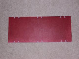
 | Cut
the Fiberglass 12x24 sheet down to 10"x24" using a table saw. Drill
the1/8" holes for suspension mounts and bearing/support brackets using
a drill press. (holes are tough to see, but they are there). Filed a grove for the lower suspension arms. |
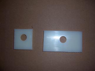 | Cut
and drill 11/16" holes in nylon brackets for axle mounts. Brackets are 2-1/4"
high and 4" and 2" wide (the bigger one goes flush against the
suspension mount. An extra indentation was added into the large
bracket (using a grinder) for the lower suspension arm since it rubbed
against the bracket. |
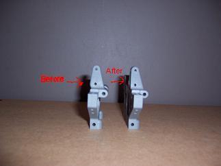 | Grind
backs of shock mounts so they can lay flush against the nylon bracket. |
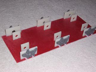 | Mount
inner and outer brackets and mounts onto board using 3x10mm screws.
Used 7/64" drill for screw holes into the nylon. The 7/64"
was small enough that the 3mm screws self tapped and locked into the
nylon. |
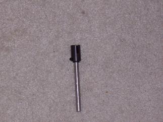 | Drilled
the 6mm hole in the axle connector to be 1/4". This was much
tougher than anticipated. Went through about 5 drill bits.
The axle connector was very, very tough. |
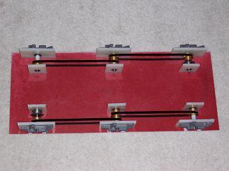 | Inserted 1/4" bearings (11/16" od) into the brackets. Inserted axle with timing belts and pulleys into the bearings. |
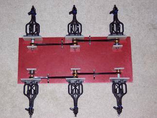 | Attached wheel arms to the mounts using Traxxas suspension pins. |
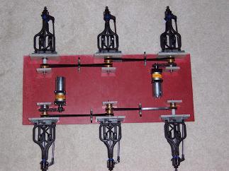 | Mounted Banebot motors using 10-30 bolts. Motors are connected to drive train using sprokets and ansi 25 chain. |
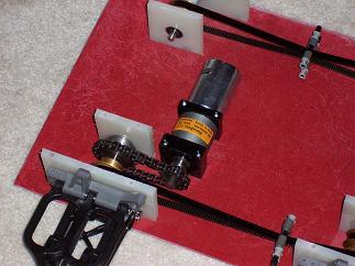 | Close up of one of the motors. |
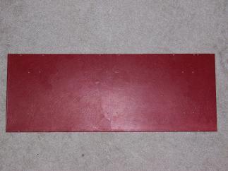 | Cut and drilled middle fiberglass plate (12"x24"x3/32" thick). Cut it to 9"x24". |
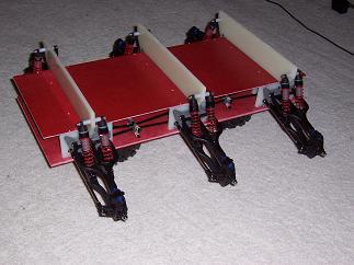 | Attached middle plate, shock support arms, and shocks. |
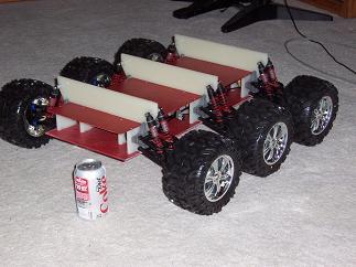 | Added wheels. |


